Search

logotype
  • Home
  • About Us
  • Where to Buy
    • Mining
    • Utility
    • Other
  • Languages
    • Spanish
    • Portuguese
    • French
  • Latest News
  • Events
  • Contact Us

Search

logotype
  • Home
  • About Us
  • Where to Buy
    • Mining
    • Utility
    • Other
  • Languages
    • Spanish
    • Portuguese
    • French
  • Latest News
  • Events
  • Contact Us
logotype
logotype
  • Home
  • About Us
  • Where to Buy
    • Mining
    • Utility
    • Other
  • Languages
    • Spanish
    • Portuguese
    • French
  • Latest News
  • Events
  • Contact Us
15 kV Cable Couplers

15 kV Cable Couplers

Download attachments:
15kV P&C Coupler Data Sheet

Category: Patton & Cooke Series
  • Description
  • Features
  • Specs
  • Options

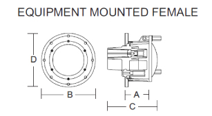
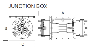
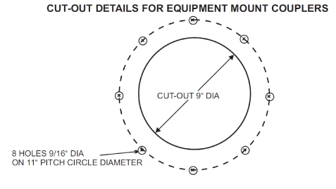
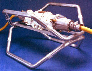
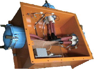
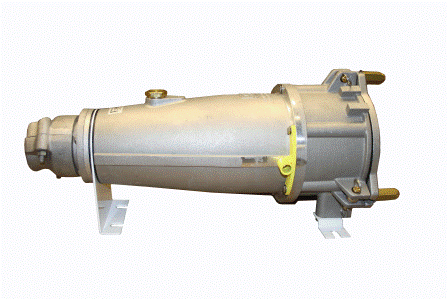
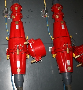
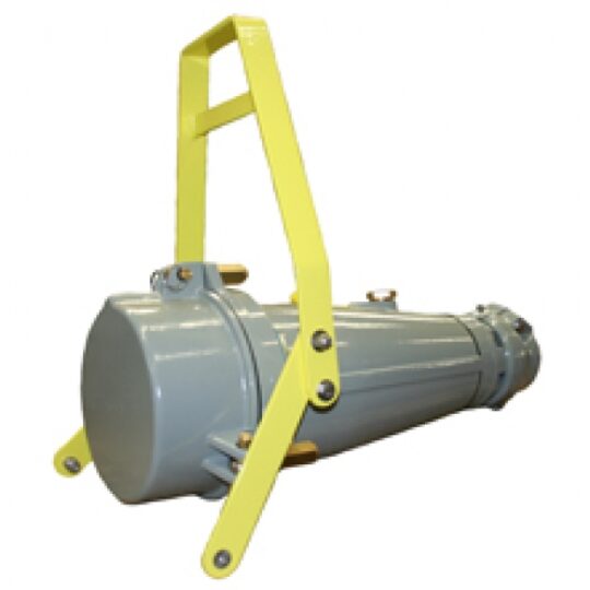
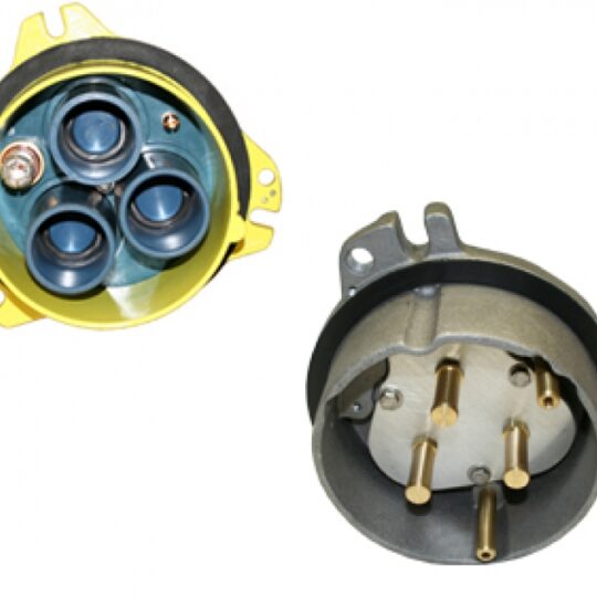
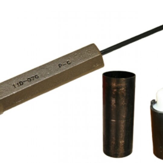
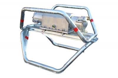
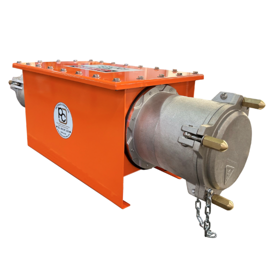
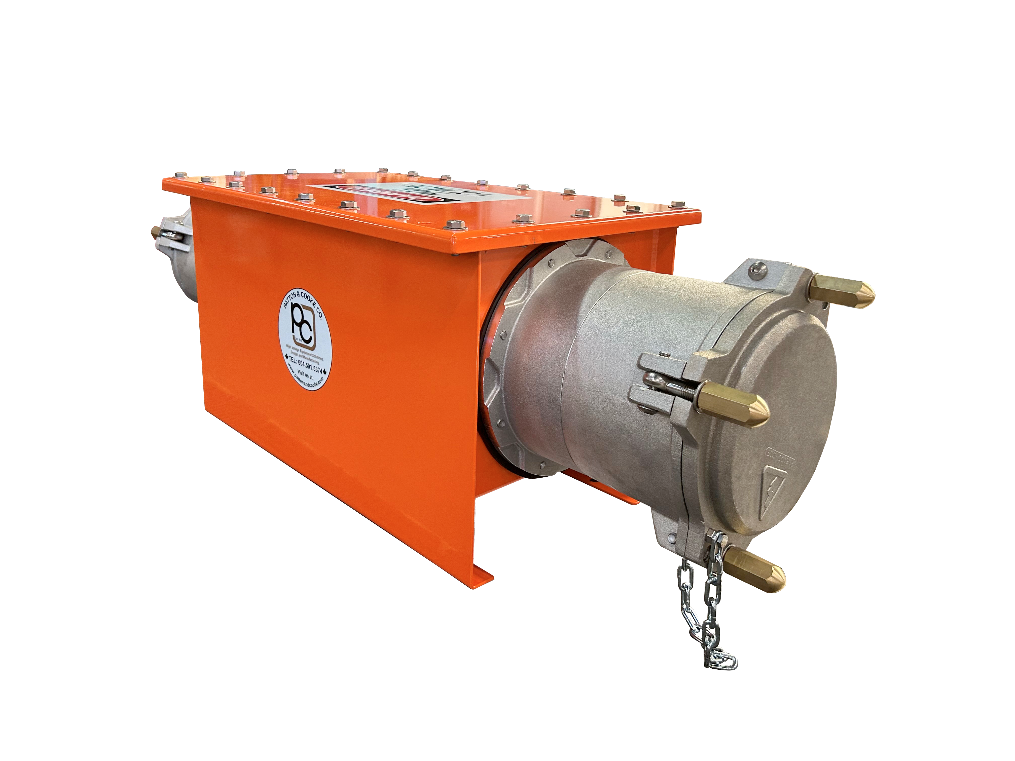
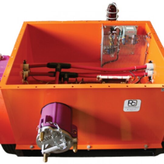
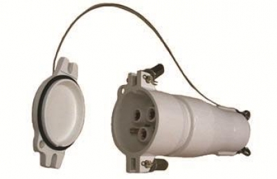
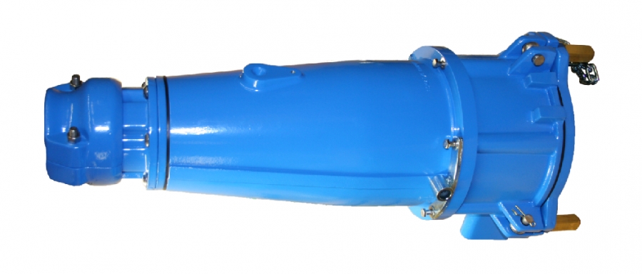
For higher voltage applications Patton & Cooke Co offers the 15 kV, 500 Amp series trailing cable coupler. A rugged and dependable performer, the 15kV coupler features a round body design and fits right in with the Patton & Cooke 600 Volt and 8kV couplers.

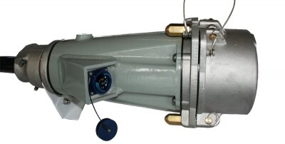
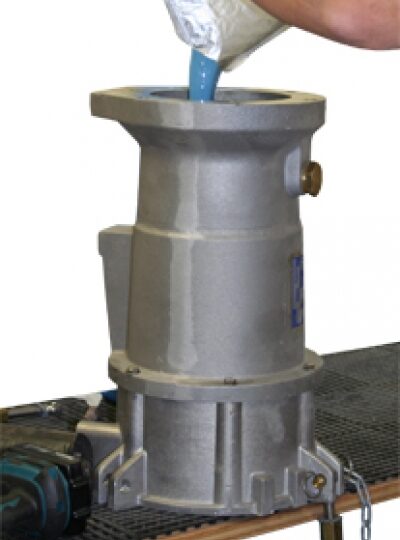
Our designers have ensured that the 15 kV unit can be configured for interchangability with other couplers of North American design. Or, using our conversion kits, update your threaded body couplers to Patton & Cooke quick flip style in just a few minutes. With its compact and front-end removable contact design, the 15 kV coupler can easily be rebuilt for longer life and long term cost savings.

Features

15 kV Cable Couplers

Patton & Cooke C150 Series 15 kV 500 Amp couplers are one of the most versatile and widely used couplers in the world. Already the standard for mining applications, Patton & Cooke is proud to have the C150 series trailing cable coupler serve as a model for the first-ever, medium voltage cable coupler standard.

We Listen to our Customers 

You asked for it and we did it… Designing and manufacturing electrical connectors for 55 years, Patton & Cooke knows that different applications require different solutions. For that reason, our 15 kV couplers offer the widest range of features and options available in the industry. Because of our design and manufacturing flexibilty, we can incorporate new features and enhancements and offer them at reasonable prices – and the features we incorporate typically save customers time, energy, and money over the life of the product. Just look at a few of our most popular features and requested options:

* 3 Bolt “Quick-flip” front body

* Front-end serviceable contacts

* Medially located ground shield

* Mechanical interlocking

* Integrated fiber optic cable connection

* Custom contact configurations

Patton & Cooke’s C150 Series trailing cable couplers are a versatile, dependable, and customizable coupler that will provide a safe and lasting performance for your medium voltage application. Check our all of the features that we offer in this coupler, and if you don’t see what you need – contact us and we will work with you to incorporate your requirements.

Specs

15 kV Cable Couplers

15kV CLASS ELECTRICAL TEST DATA:


STANDARD CONTACT ARRANGEMENT:
Contact Structure: 3 Power + 1 Ground + 1 Pilot

CABLE & CONDUCTOR RANGE

#2 – 500 MCM AWG or 34 mm2 – 254 mm2

CABLE DIAMETER

0.82″ – 3.50″ or 21 mm – 90 mm


500 AMP COUPLER WEIGHTS & DIMENSIONS:
15kV_CableMountMale

A B C Weight
20 1/4″ 10 1/2″ 24 1/2″ 38.0 lb
514 mm 267 mm 622 mm 14.5 kg

15kV_EquipmentMountMale

A B C D E Weight
4 3/4″ 12 1/4″ 9″ 11″ 1 1/2″ 32.0 lb
121 mm 311 mm 229 mm 279 mm 38 mm 14.5 kg

15kV_CableMountFemale

A B C Weight
24″ 11 1/2″ 27″ 38.0 lb
610 mm 292 mm 686 mm 17.0 kg

15kV_EquipmentMountFemale

A B C D E Weight
5 1/4″ 12 1/4″ 8 1/4″ 11″ 4″ 27.0 lb
133 mm 311 mm 210 mm 279 mm 102 mm 12.3 kg

15kV_junctionbox

A B C Weight
16 1/4″ 14 1/4″ 32″ 100.0 lb
413 mm 362 mm 813 mm 45.0 kg

CutOutDetailsEquipmentMountCouplers

 
Max Cable Size

SHD-GC 15 kV

x – Cat. No.

Suffix

34 mm2 #2 F
42 mm2 #1 G
54 mm2 1/0 H
67 mm2 2/0 J
85 mm2 3/0 K
107 mm2 4/0 L
127 mm2 250 MCM M
152 mm2 300 MCM N
178 mm2 350 MCM O
203 mm2 400 MCM P
228 mm2 450 MCM Q
254 mm2 500 MCM R


SELECTION REMINDERS:

  1. Couplers are standard equipped with solder type stems.Solder stems will be sized to accommodate the conductor size specified.
  2. All couplers and junction boxes are supplied with cover, attachment chain and provision for padlocking.

ORDERING PROCEDURE:

  • Determine the following:

Male (plug) or female (receptacle) contacts Cable or equipment mounting

  • For equipment mounting, select catalog number of coupler.
  • For cable mounting, determine outside cable diameter and provide this information on order for entrance fitting kit selection.
  • Provide the conductor size with order

Example:

Male plug, cable mount,  #2 AWG cable, outside cable diameter 2.54″

Coupler Cat No: C150F1005F

Entrance Fitting Kit Cat No: C150F3020

Options

15 kV Cable Couplers

AVAILABLE OPTIONS AND ACCESSORIES


MECHANICAL INTERLOCKING

Benefits: One of the most effective methods to prevent decoupling of energized couplers

Mechanical interlocking is one of the most reliable means for promoting and ensuring safety   around high voltage electrical equipment. By design, 15 kV class couplers are not intended to be disconnected when energized. There are safety features incorporated into these products to prevent disconnecting couplers under load, as well as features to limit the danger in this event. However, utilizing a mechanical interlocking   arrangement in combination with the 15 kV design features, and safety procedures, provides further protection for personnel and equipment.

Click here for more information on interlocking


EPOXY POWDER COATING

Benefits: corrosion resistance, visual identification

Epoxy Powder coating provides a strong and corrosion resistant finish to aluminum coupler bodies and castings. While Patton & Cooke use alloys with the highest possible corrosion resistance, for corrosive environments such as heap leaching, marine, or underground mines with acidic conditions, Patton & Cooke recommend an epoxy powder coated finish to maximize the life of the project. Powder coating is also an effective visual indicator of coupler gender. To help reduce cable laying errors, a basic color coding scheme can help mine personnel easily and identify male and female couplers. Standard colors are shown below, custom colors are available upon request.


JUNCTION BOX

Benefits: Skid mounted junctions can prolong cable and coupler life and enables plug / plug cable arrangement

Incorporating a plug to plug cable arrangement is the major advantage that can be gained with a junction box. For larger cables in particular, it can take considerable time and energy to add or remove a length of cable from a mining production environment. With a plug to plug arrangement, the cable can be laid out in either direction as the connector is the same on both ends. Traditional jumper cable arrangements are plug to receptacle, like common household extension cords, and so it is possible to lay out a cable “incorrectly” with this arrangement.

Click here for more information on junction boxes

skid-mount-junction


SPLITTER BOX

Benefits: Provides power and monitoring to multiple pieces of mobile equipment with less cable

Splitter boxes are the ideal solution   for reducing cable requirements in production areas.  Splitter boxes enable 2 or more pieces of equipment to draw power from 1 cable feed. Splitter boxes have  a wide range of options including indicator lights and ground wire monitoring. If equipped with optional live  end covers, it is possible to energize the splitter  box with one or more unused outlets.

Click here for more information on splitter boxes

Splitter Box

SKIDS

Benefits: Skid mounted coupler can prolong cable and coupler life

The use of skids with couplers can help   to dramatically extend the life of cable and couplers by keeping them off the ground, and increasing their visibility to personnel and mobile equipment. For personnel, increased visibility means a safer work environment;   and for equipment, it means less downtime.

Patton & Cooke couplers are designed to ensure a long working life if they are left on the ground, however skid mounting couplers will provide added protection for the cable and couplers. And as the real cost of coupler ownership includes installation,   maintenance, and materials, extending the life of couplers will help to reduce these costs as well.

Extending the life of couplers means less maintenance and more machine uptime!

Skid

Click here for more information on skids


LIVE END COVER

Benefits: Enables splitter boxes to be safely energized with 1 or more circuits disconnected

Live end covers were designed for use with splitter boxes equipped with ground wire monitor protection devices. Live end covers provide incorporate protective covers, insulated phase tubes, and end of line devices which enable safe energization of a splitter box even if one or more circuits have been disconnected.

58kV Live End Cover

Click here for more information on Live End Covers


MOUNTING HARDWARE

Benefits: Simplify the installation   process for equipment mounted couplers by ordering mounting hardware with your coupler

C80 Series Panel mount couplers are not supplied with hardware for mounting to equipment or enclosures. The size of the hardware will depend on the thickness of the enclosure wall. To mount your coupler you can obtain hardware equivalent to the sizes indicated below. Patton & Cooke can supply these as well as an optional accessory with the part number

For an enclosure with 1/8″ – 1/4″ wall thickness the following mounting hardware kit is recommended:

(8) GB-0814 : 1/2″ x 1-3/4″ Galvanized bolts

(16) GFW-08 : 1/2″ Galvanized flatwasher

(8) GLW-08 : 1/2″ Galvanized lockwasher

(8) GN-08 : 1/2″ Galvanized nut

Kit Part Number: C80F3xxx


ELBOW / MOUNTING ADAPTERS

Benefits: Reduces strain on enclosure and cable

Patton & Cooke recommend using 3/8″ hardware for gear mount couplers and 1/2″ hardware for flange mount couplers to help ensure a robust installation and to help maintain IP protection in mining, industrial, and marine environments. However incorporating elbow adapters with gear and flange mount couplers can reduce strain on the enclosure and the cable, helping to maximize the performance and service life of your equipment.


LEG MOUNTING

Benefits: Provides versatility for mounting couplers in fixed installations

For applications where a cable mount coupler can be stationary such as when mounted to a wall, an accessory, or a piece of mobile equipment, Patton & Cooke offer the leg mounting option. Leg mounts brackets are made of mild steel and are powder coated for additional corrosion protection. Brackets are provided in a standard size, but custom or modified versions are available upon request. Couplers can be mounted in vertical or horizontal orientation.

leg mount coupler for skid Leg mount coupler vertical suspension


FIBER OPTICS

Coupler Features:

  • Enhanced entrance fitting combines strain relief and cable seal
  • Solder, solderless, or crimp style contact stems
  • Standard couplers supplied with two piece contacts for ease of maintenance
  • Customizable contact arrangement
  • Individually replaceable phase tubes
  • Fully shielded phase conductors
  • Optional one piece contacts for extreme vibration resistance
  • Stainless steel quick flip coupling eye bolts
  • Heat treated, cast aluminum body

Fiber Features:

  • Patton & Cooke fiber optic components are designed to exceed military specifications
  • Three times the crush resistance and twice the tensile strength of non-metallic fiber optic cables
  • Communication is not impacted, even if rolled over by a tank
  • Completely rodent proof
  • Contamination resistance – designed for field connection and disconnection
  • High performance 2.5 mm termini and a split ceramic alignment sleeve assures superior performance and low optical inseration loss even under high shock and vibration
  • Aluminum body with durable anodized finish
  • Stainless steel construction available
  • Environmental sealing to IP68
  • APC termini optional
  • Singlemode and Multimode operation
  • Configurable design supports from 2-18 fiber channels per connector
Electrical Characteristics
Nominal voltage 15 kV AC
a.c. withstand voltage 50 kV dry (1 min)
Impulse a.c. withstand voltage 95 kV (10 pos, 10 neg)
Partical discharge (for high-voltage equipment) 100pC @ 21.5 kV
Nominal current 500 Amps
Short circuit rating 38 kA
Short time short-circuit withstand capacity 13.5 kA for .2 sec
Peak withstand 28 kA
Mechanical Characteristics
Enclosure degree of protections IP67H
Acceptable cable cross-sectional area 500 MCM/240 mm max.
Construction materials Aluminum
Ambient temperature -40°C to +45°C
Shock and vibration IK10

For more information on 15 kV Cable Couplers, please contact:
Patton & Cooke Co.

You may also like…

Fiber Optics
Read more

Fiber Optics

Potting Compound
Read more

Potting Compound

Closing Tools
Read more

Closing Tools

Enhanced Safety Covers
Read more

Enhanced Safety Covers

Termination Kits
Read more

Termination Kits

Cable Stands
Read more

Cable Stands

Coupler Tool Kits
Read more

Coupler Tool Kits

Skids
Read more

Skids

Junction Boxes
Read more

Junction Boxes

Splitter Boxes
Read more

Splitter Boxes

Related products

600 Volt Cable Couplers
Read more

600 Volt Cable Couplers

Categories
  • Mining35
    • Trailing Cable Couplers9
      • Patton & Cooke Series5
      • IMG Series4
    • Cable Protection5
    • Cable Support6
    • Electrical Components6
    • Fibre Optics1
    • Installation Materials5
    • Tools3
  • Utilities31
  • Shore Power4
  • Tunneling1
  • Transportation3
Download Brochures
Utility Industry  PDF


Ship to Shore PDF

Mining PDF

Tunneling PDF

Mining PDF
Patton & Cooke Co.
  • Home
  • About
  • Where to Buy
  • Events
  • Languages
  • Contact Us
Upcoming Events:
About Patton & Cooke Co.

Patton & Cooke was founded in 1961 by an electrical engineer and an electrical designer. Their guiding principle was simple: …read more

Contact Us:

For information please contact us at:

  • Email: info@pattonandcooke.com
  • Ph: 604-591-5374
  • Fax: 604-591-3505
  • Address:
    Unit 100 – 7795 128th Street, Surrey, B.C. Canada V3W 4E6

Copyright © {2023} Patton & Cooke Co.